|
GNSS Receiver, Antennas and Front Ends
Global Navigation Satellite Systems (GNSS) are satellite-based systems that enable users to determine their position and velocity on a global scale. These systems consist of various segments, including the control segment, space segment, and user segment. In recent years, there has been a significant increase in the use of navigation systems across different applications and devices. For the purpose of this dissertation, our focus will be on the user segment and the civilian utilization of GNSS.
Overview and Concept Many countries have either established or planned to establish their own national or regional Global Navigation Satellite Systems as part of their space programs. In each GNSS system, a control station serves as the master station, responsible for adjusting the satellite orbit parameters and ensuring high accuracy by regulating the on-board precise clocks. Monitor stations are strategically placed across a wide geographic area to monitor the status of satellite signals. The master control station analyzes information received from each monitor station and sends orbit and time corrections to the satellites, which orbit at an altitude of around 20,000 km above the Earth, through data uploading stations. Each GNSS satellite forms its own constellation to provide the desired coverage, while user equipment on Earth can range from handheld devices to sophisticated, specialized receivers used for mapping applications.
The applications of GNSS have significantly expanded in recent years, encompassing various fields such as agriculture, transportation, machine control, and marine navigation. Additionally, GNSS systems offer a valuable synchronization capability, where user receivers can synchronize their local clocks with the highly precise clocks of the satellites. This synchronization enables the coordination of power grids, cellular networks, and financial networks. As GNSS technology continues to improve and become more affordable, the number of applications conceived and developed is expected to increase. Nowadays, both ordinary users and professionals demand more reliable and accurate products. Therefore, it is crucial to provide systems with a high level of security to meet both current and future requirements. While GNSS technology is widely popular and accessible to the public, it is important to investigate its vulnerabilities and develop appropriate methods to counteract them. This website aims to explore these aspects and serves as one of the motivations for initiating this topic.
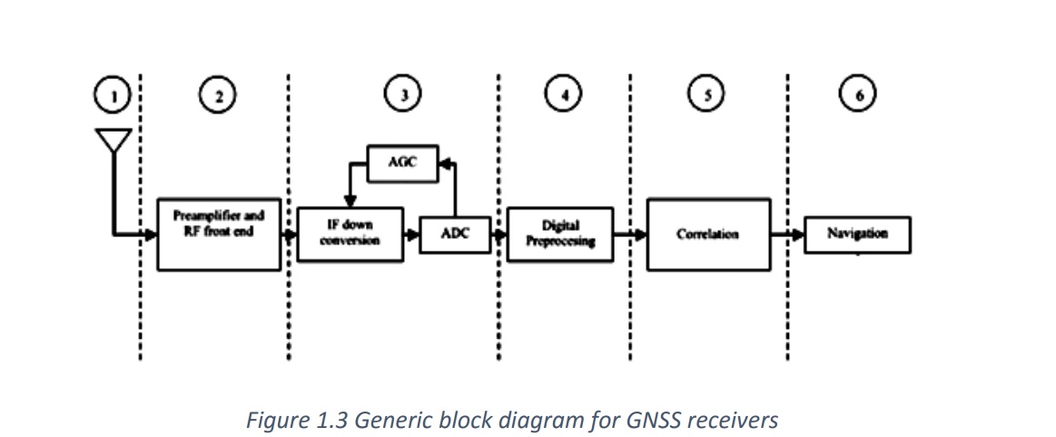
The ability to differentiate between components and units of a GNSS receiver is crucial as it helps us categorize interference techniques in the subsequent chapters. Figure 1 illustrates a general block diagram depicting the architecture of a GNSS receiver. The fifth stage, known as the correlation step, plays a vital role in classifying detection and mitigation techniques. Pre-correlation and post-correlation techniques refer to the specific stages where these techniques are implemented. In the following sections, we will provide an overview of each step to gain a deeper understanding of GNSS receiver architecture.
The first stage of a GNSS receiver is the antenna. When discussing antennas, three fundamental parameters should be considered: frequency/bandwidth, polarization, and gain pattern.
Typically, in the L1 or 1575.42 MHz band, all frontend components have an impedance of 50Ω and are divided into two types of antennas: active and passive. Passive antennas are used in designs with analog amplifier receivers. Ordinary handheld devices with GNSS receivers often employ active antennas, which are considered active elements and require power for the internal amplifier. This power is supplied through a bias-tree component, which injects DC power into the antenna cable to activate the amplifier. Preamplifiers, unlike most filters, are active components that require power to carry out their functions. Amplification in this structure is not only based on signal amplitude but also on the resulting signal's noise. The purpose of using an amplifier in this setup is to amplify the extremely weak incident signal to a level suitable for analog-to-digital conversion. The amount of amplification depends on the specific ADC used in the receiver.
The Analog-to-Digital Converter (ADC) is responsible for converting the analog signal into digital samples. When selecting the appropriate ADC, key parameters such as the number of bits, maximum sampling frequency, analog input bandwidth, and analog input range must be considered. There is a wide variety of ADCs available in the market to suit different requirements. For example, in the case of GNSS with its modulation scheme and CDMA nature, ADCs with a small dynamic range for the sampled signal could be an option. It has been demonstrated that using single-bit sampling results in less than 2 dB degradation in the front-end process. Therefore, it is important to determine if multi-bit sampling is used, and if so, a form of gain control is needed to ensure proper quantization.
The digital preprocessing stage is responsible for sample preprocessing before the actual correlation process takes place. Filters may be applied to achieve optimal tracking performance, and the noise floor needs to be determined. It is worth noting that many of the detection and mitigation techniques that will be presented later are implemented in this unit.
The correlator unit is the key operational unit in GNSS receivers, as it synchronizes the local signal with the incoming signal, generates GNSS observables, and retrieves the navigation message necessary for providing a navigation solution in the subsequent navigation unit.
The navigation unit is responsible for accurately determining the user's position and velocity. Once the signal is acquired and tracked, the computation of the user's position and velocity begins with respect to the receiver's reference clock. |